
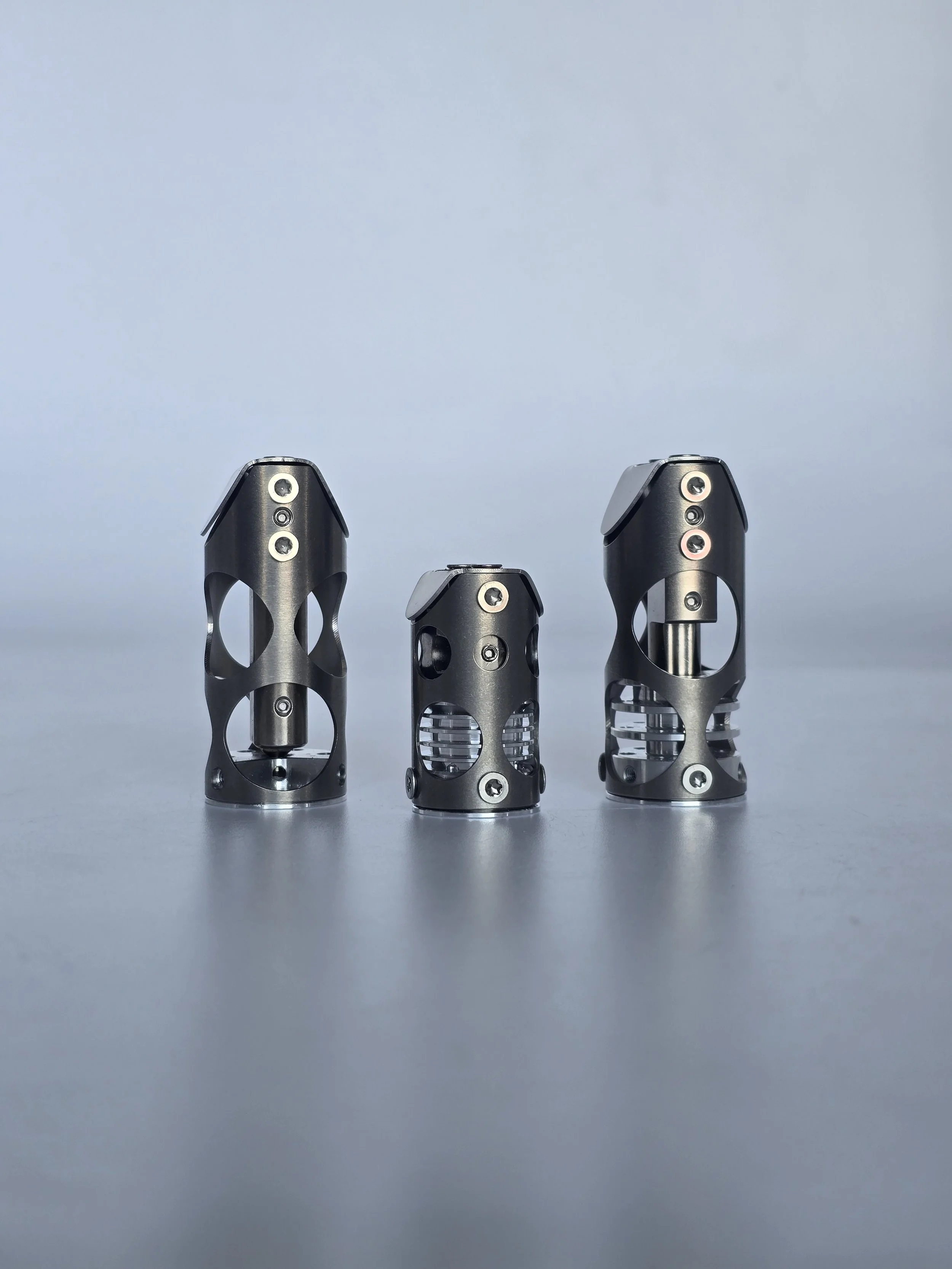
CHUBE INTEGRATION
CHUBE INTEGRATION
Chube Air and Conduction Integration CAD:
CLICK HERE
Chube Compact Integration CAD:
CLICK HERE
-
General Recommendations:
We suggest using all 6 bolts to mount the Chube Air and Conduction to your printer, all 4 for Chube Compact.
Size your heater appropriately with proper safety precautions.
Ensure your wires exit appropriately and are properly restrained.
Make sure your wires are properly crimped.
-

Chube Compact:
Please ensure there is an appropriate inlet and outlet for airflow.
The life of your silicone sock will deteriorate much faster past 300C.
Using a heater wattage higher than 80w is not recommended.
Always make sure off-the shelf components can safely reach the temperatures you plan to print at.
If designing custom toolhead, keep heater placement in mind for ease of use.
-

Chube Air:
Please ensure there is an appropriate inlet and outlet for airflow.
We recommend aligning it directly with a single hole and allowing it to exit out the sides of the rear off-axis holes.
Fairly low cooling requirements - almost all 2510 fans will cool sufficiently.
If mounting to plastic - please ensure proper safety precautions are taken with heatsink fan/temperature.
-

Chube Conduction:
Please ensure there is sufficient heat rejection in the system the Chube Hotend is mounted to.
Requires 80cm^2 of exposed surface area at room temperature to properly cool.
Do not mount this to non-thermally conductive material.
Please ensure that all connected parts can sustain heightened temperatures due to the nature of how the hotend will be cooled.

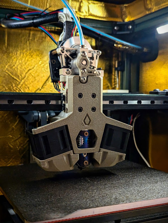
Takeoff Toolhead - For Chube Air and Conduction. This toolhead was designed by Burgo, and can be found on Github, at Luke's Laboratory, or at 3DKatten in Sweden.

Ratrig VC4 Toolhead, for Chube Air. This toolhead was designed by Burgo, and can be found on Github, Luke's Laboratory, and at several other vendors.

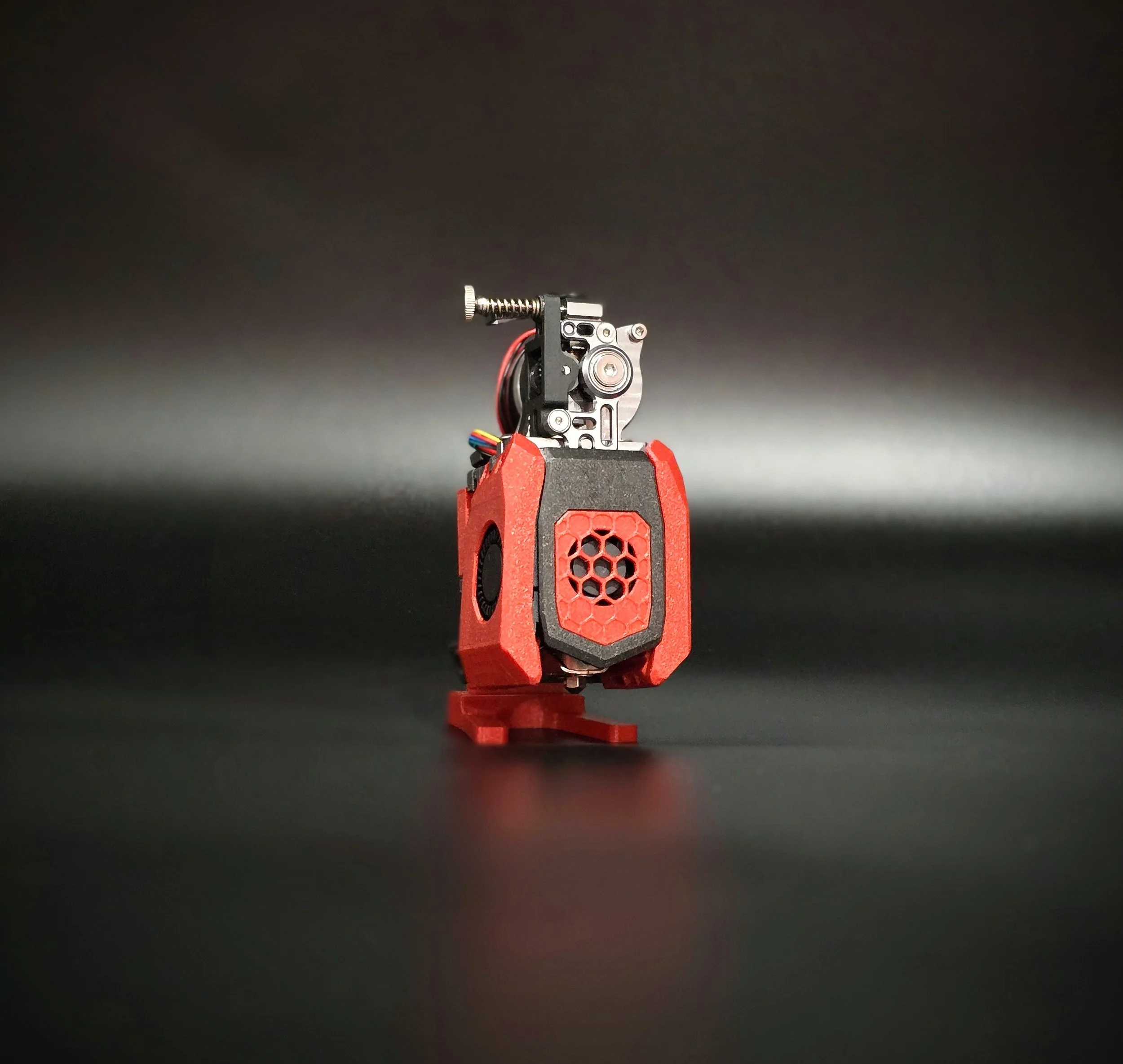
Calamity Toolhead is compatible with Chube Air, Conduction, and Compact. The toolhead is open-sourced, and designed by Luke of Luke's Laboratory. Kits are available at Luke's Lab.
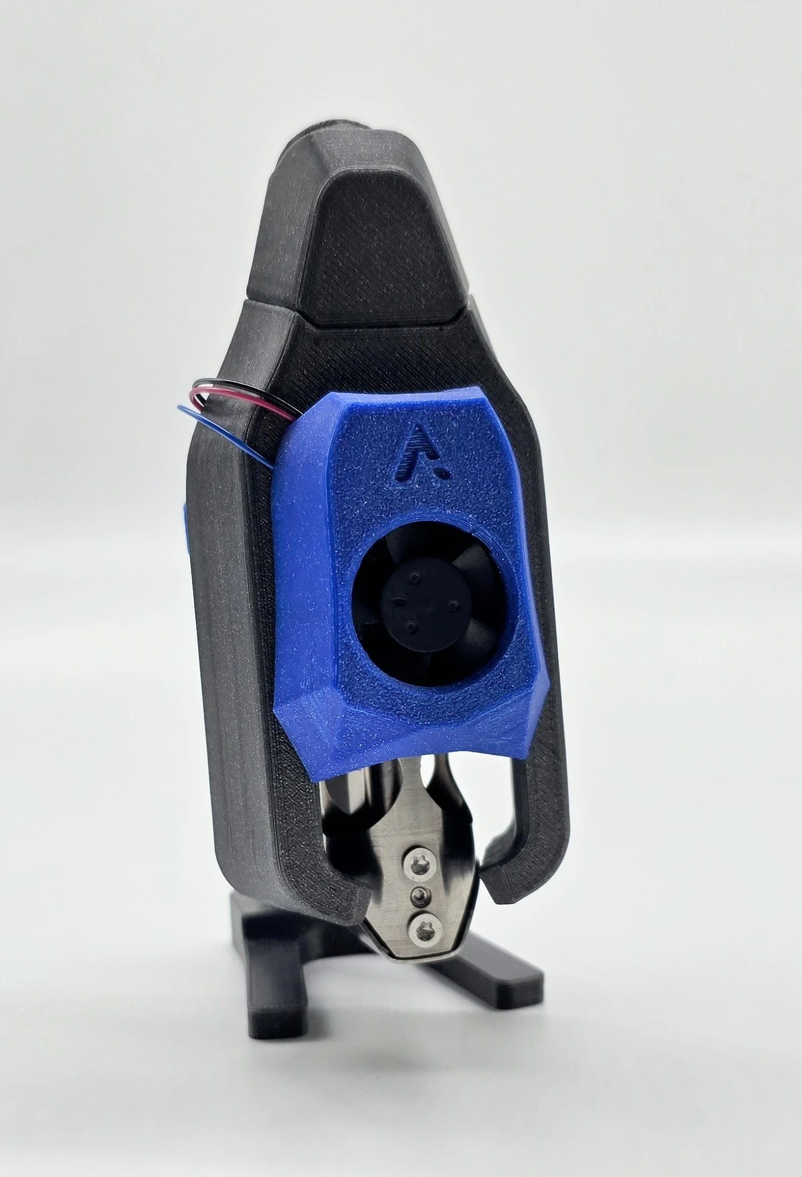
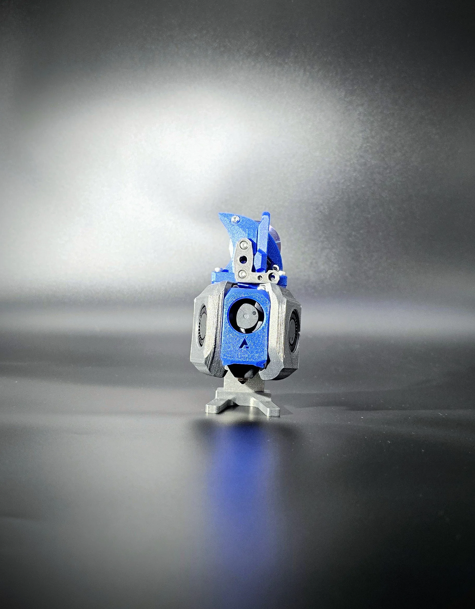
Archetype Toolhead - By Leddhead For Chube Air

Chube CHAMP for Chube Conduction CHAMP Design by: Luke Ashley - Luke's Laboratory

Elegoo Orangestorm Giga Upgrade Toolhead Design: Luke Ashley - Luke's Laboratory

Chube Air Waterblock Waterblock Design: Luke Ashley - Luke's Laboratory

Chube Conduction Waterblock Waterblock Design: Luke Ashley - Luke's Laboratory

Chube Compact Annex K3 Toolhead Original Toolhead Design: Mathematical Potato Photo and Build: Danni

Stealthburner Toolhead For Voron Chube Compact Photo: Audrina Ashley - Luke's Laboratory

Chube CHAMP for Compact
Trinity Toolhead for Compact, designed by Prooda and Gerbz

Dragon Burner V8 - Chube Compact Integration - BakedBean3D
Anthead for Chube Compact by HartK
Archetype Toolhead for Chube Compact by Leddy

A4T Toolhead by DW Tas